Solar plants are changing. From one-size-fits-all towards well-adapted systems that give better technical answers to the most common (cost) problems. With these posts I’d like to contribute with new solar technologies that I’ve developed over the last couple of years.
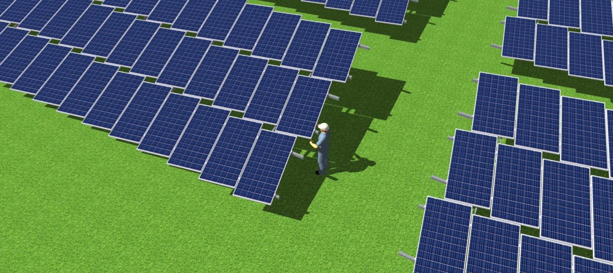
In my previous articles I’ve shown several variations of the X-panel solar technology where the solar modules are neither installed in a portrait nor in a landscape orientation, but in a position “in between”. These arrangements all help the solar panels to stay clean due to better evacuation of (dirty) water.
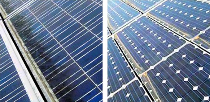
The reason is: Most of today’s solar panels are embedded in aluminum frames. At low slope angles the lower frame rail of the panel builds a horizontal raised rib at the lower edge of the module. This rib causes a back-water effect. The filthy water is not correctly run off resulting in the accumulation of dirt on the glass alongside the lower frame rail (see picture). This often results in significant loss in yield.
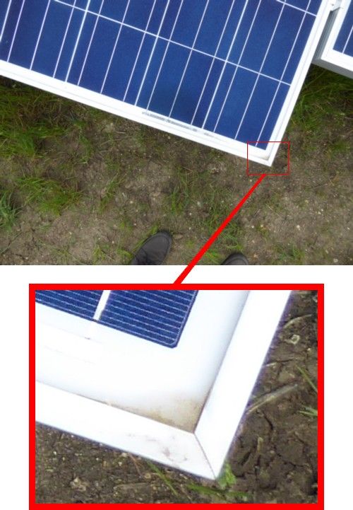
Leading solar project companies like ENERPARC declared that as far as the module angle, 20° was the “magic number”. They didn’t go flatter to avoid soiling losses. Now they do because with the new X-panel arrangement the horizontal corrugation disappears. The lower frame rails now both show slopes ensuring proper runoff of rainwater. Thus the panel will remain clean, even at slope angles of only a couple of degrees. There will be a visible triangular spot in the very corner of the panel. This spot, however, is far away from the lowest cell, so it cannot hurt the panel’s energy yield (see picture).
X10 panel arrangement

Although the solar modules are rotated, the defined clamping zones (coloured in green) are fully respected.
The X10 panel arrangement might be the simplest and most cost effective variation of all X-panel technologies. We call it X10 as it looks like a panel in portrait position that has been rotated some ten degrees (clockwise or counterclockwise). However, the precise rotation angle depends on the clamping zones that are specified by the panel manufacturer. Therefore the maximum rotation angle varies from module to module. Typical clamping zones for a solar panel are the span between 1/4 and 1/8 of the length of the module, measured from the corners, e.g. the zone between 200 mm and 400 mm for a standard 60 cell solar panel. The X10 geometry uses the full range of these clamping zones by rotating two adjacent panels just to that point where the clamping zones overlap just enough to place the middle clamp in a way that the clamp is within both clamping zones, left and right (see picture, clamping zones are marked in green). The larger the allowed clamping zone, the more you can rotate the module while respecting the manufacturer’s specifications.
This installation technology allows for very economical racking structures under the panels since they’re pretty identical to those used for standard portrait installations. Same horizontal rails, and in most cases even the same module clamps. Therefore there’s no need to manufacture specific parts to install X10, so the cost per kWp are very convenient. A X10 racking will cost the same as a standard racking where panels in portrait are mounted on two horizontal rails.
shifted X10 panel arrangement
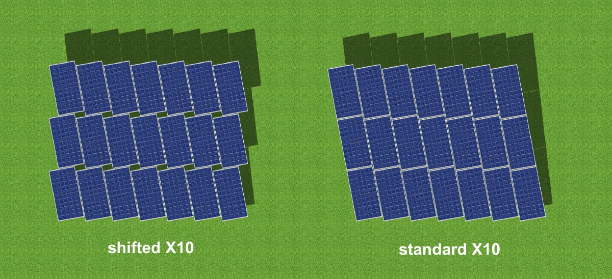
It should be noted that – given by this unique panel arrangement – the top view on a module table changes. While module tables for standard installations show a rectangular shape, those for X10 systems show a parallelogram. This will not have any technical consequences, so it should be perfect for almost all ground mounted solar projects. There is, however, a way to get the panel tables „rectangular“ with X10. The procedure to achieve this is to offset the horizontal module lines against each other in a way that the corners of the outer panels are again lying on a rectangular line (top view). We call this the „X10 shifted“ arrangement.

Standard X10 module arrangement (right) produces module tables in form of a parallelogram, while in the shifted version the module tables are rectangular in top view.
No only does X10 shifted look quite different from how solar things have been done in the past, this arrangement has two more important advantages: better aerodynamic properties and improved cooling of the solar panels. The reason: The shift produces rectangular gaps between the modules. These gaps reduce the wind loads since they help to equalize pressure differencies between the upper and the lower side of the module table. Think of a sailing ship with perforated sails. The result is an improved exchange of air, which in turn will very likely help to cool the panels. Less loads, better cooling – and all without extra cost for the racking under the modules.
Main benefits of shifted X10
- perfect self-cleaning capabilities for reliable energy yields
- lower module angles for higher ground coverage ratios
- less wind loads due to special gaps between the modules
- better module cooling
- off-the-shelf hardware, easy installation reduced
- maintenance cost, lower electricity cost (LCOE)


